
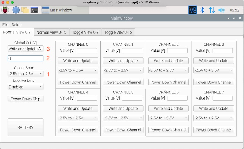
Quick Start
- Select the Global Span Value [1]
- Write voltage on the Global Set field [2]
 Global set voltage
– Click Write & Update All pushbutton: the same value will be set on all channels [3] and all outputs will be updated.
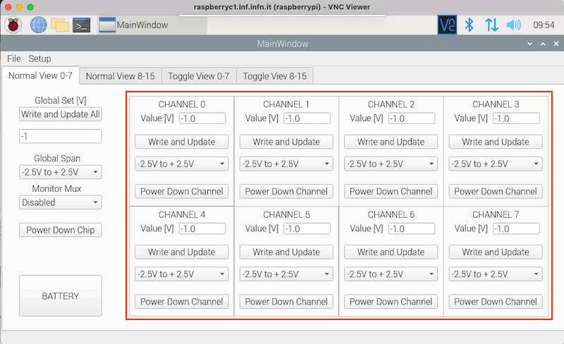 After Write & Update the Value will be set on all channels
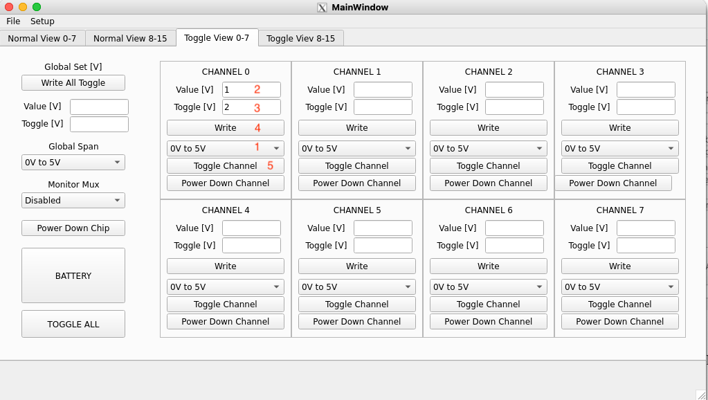
- select the Global Span Value [1]
- set Normal value and Toggle value in Global fields [2,3]
- click on Write All toggle button [4]
- click on TOGGLE button [5]; all channels DAC values will switch between Normal and Toggle values
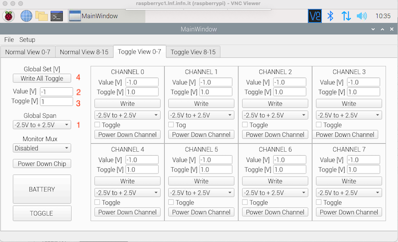 Set voltages for Toggle operation
- set Voltage Span value in the selected channel [1]
- set Voltage value in the selected channel [2]
- click on Write and Update button [3]
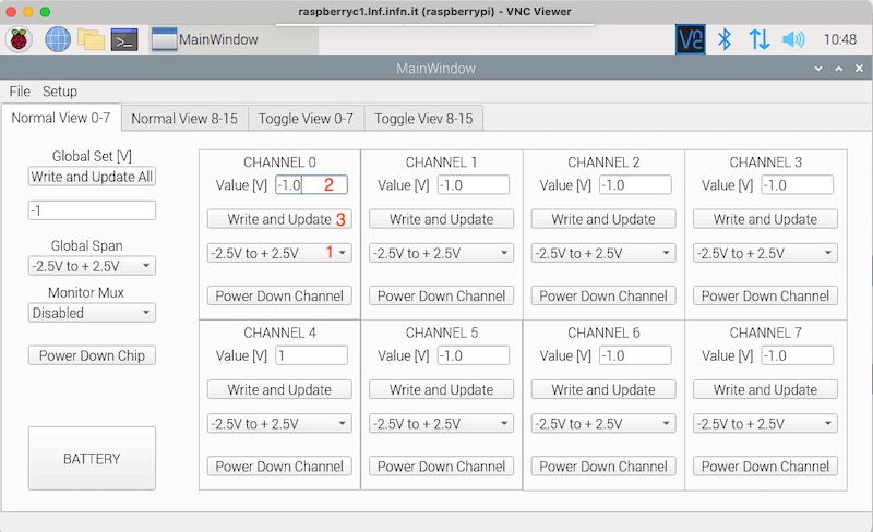 Set CH4 in Normal Operation
- Set channel span [1]
- Set channel voltage channel Normal and Toggle voltage [2,3]
- Click Write and Update [4]
- Click on TOGGLE button [5]; the channels DAC value will switch between Normal and Toggle values
Set CH4 for Toggle Operation
- In Normal or Toggle operation the “Power Down Chip” pushbutton will clear all the outputs and the setting values [1]
- The “Power Down Channel” has the same function at channel level [2]
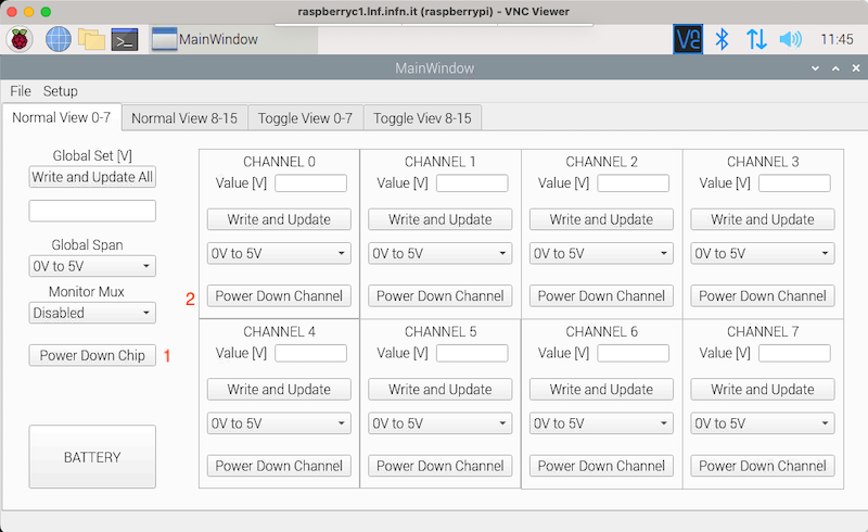
Power Down All and Single Channels
In the Battery Operation mode the analog section is fully decoupled from main power while the control section is still operated from main power supply. The two section are fully decoupled by means of isolators.
To enable the “Battery Operation Mode” use the dedicated pushbutton [1]
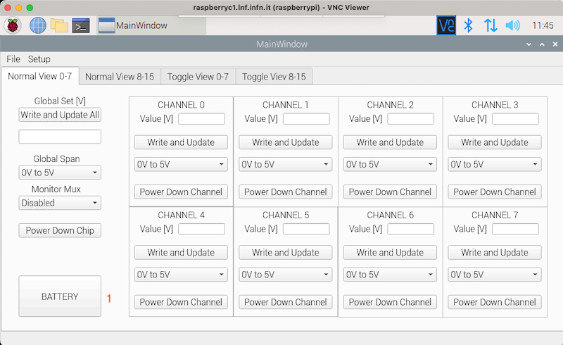
Power Down All and Single Channels
Power Down All and Single Channels
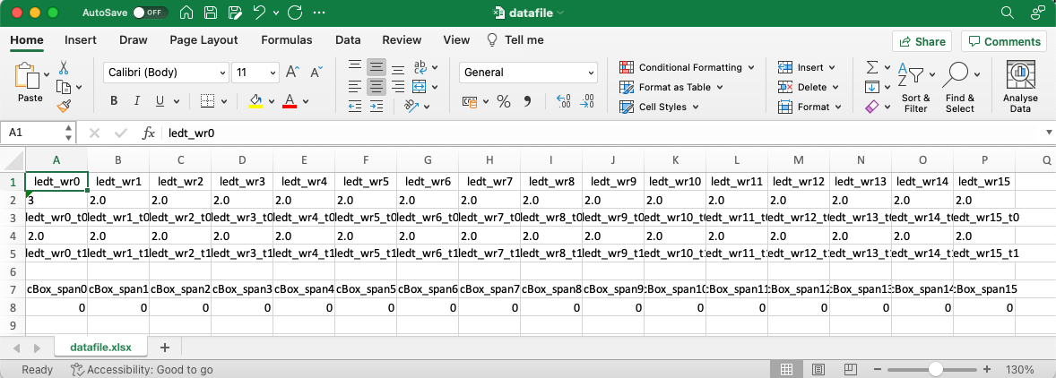
The Excel file for saving retrieving data
HARDWARE
The 16 Channels Power Supply projects is based on a LTC2668 DAC; the DAC features are shown below while the full datasheet can be downloaded from here.
LTC2668 Main Features
- Output Voltage Noise (1 kHz, internal reference): 90 nV/ √Hz
- Precision Reference 10ppm/°C Max
- Independently Programmable Output Ranges: 0V to 5V, 0V to 10V, ±2.5V, ±5V, ±10V
- Full 16-Bit/12-Bit Resolution at All Ranges n Maximum INL Error: ±4LSB at 16 Bits
- A/B Toggle via Software or Dedicated Pin n 16:1 Analog Multiplexer
- Guaranteed Monotonic Over Temperature
- Internal or External Reference
- Outputs Drive ±10mA Guaranteed
- 1.8V to 5V SPI Serial interface
- 6mm × 6mm 40-Lead QFN Package
The Power Supply is made of two fully decoupled sections (see block diagram): the DAC section and the Control section. The control section is based on a Raspberry board managed by a PyQT program.
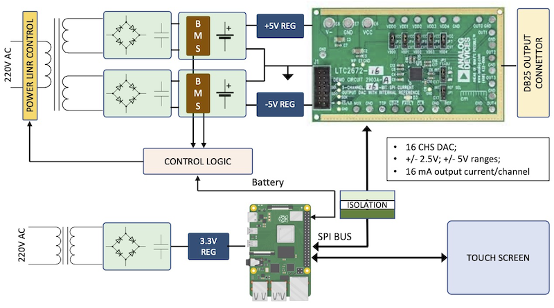
The 16 Channels Low Noise Power Supply Block diagram
The DAC Power section
A 2x6V (18 VA) transformer together with a bridge rectifier circuits are used to generate two independent supply voltages. Each voltage supplies a BMS-Li-Ion battery block with dedicated batteries. The two blocks are serially connected to provide the positive/negative supply voltage required by the DAC (NB: the common connection is implemented only at the batteries level then allowing the correct working of the BMS).
The CONTROL section
The CONTROL section is based on a RPi board with a dedicated power supply; CONTROL section and DAC section are fully decoupled by means of ISO7241 digital isolators and optcocupolers.
Operation
In normal operation mode the 220V input line is connected to both transformers then the system is full powered by the main power line. If battery operation mode is selected only the RPi supply circuit is connected to the 220V line while the DAC board powered from batteries; in this configuration only batteries. In this operation mode a dedicated circuit continuously sense the voltages forcing the 220V line mode if the batteries voltage drop below a set values. The figure below shows a more detailed scheme of the system.
The 16 Channels Low Noise Power Supply Scheme
The 16 Channels Low Noise Power Supply Prototype (top view)

The 16 Channels Low Noise Power Supply Prototype (front wives)

SOFTWARE
The system is managed by a PyQT GUI in three different ways:
- Stand Alone: connecting a keyboard (both bluetooth or wired) and taking advantage of the touch screen display to set the required values
- X-Window: this mode use SSH together with SSH forwarding to run remote X-Window applications
- VNC: use the Virtual Network Computing to control the system
As the three modes use the same GUI, here is a description of the operation using a VNC connection:
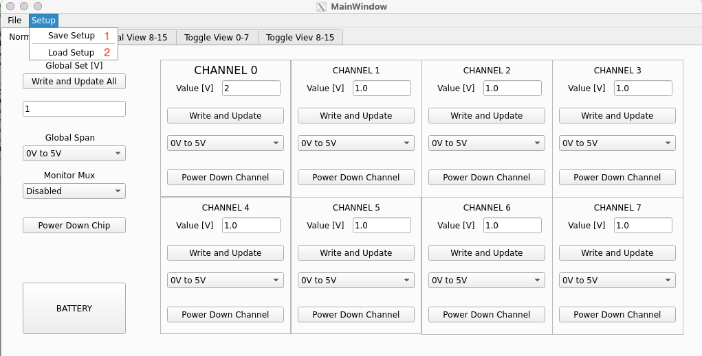
Launch of the Application
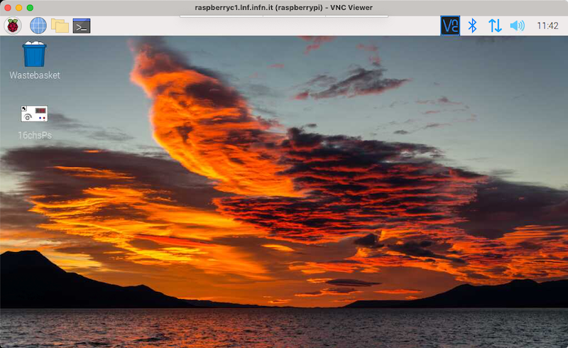
1 – Launch VNC
VNC connection
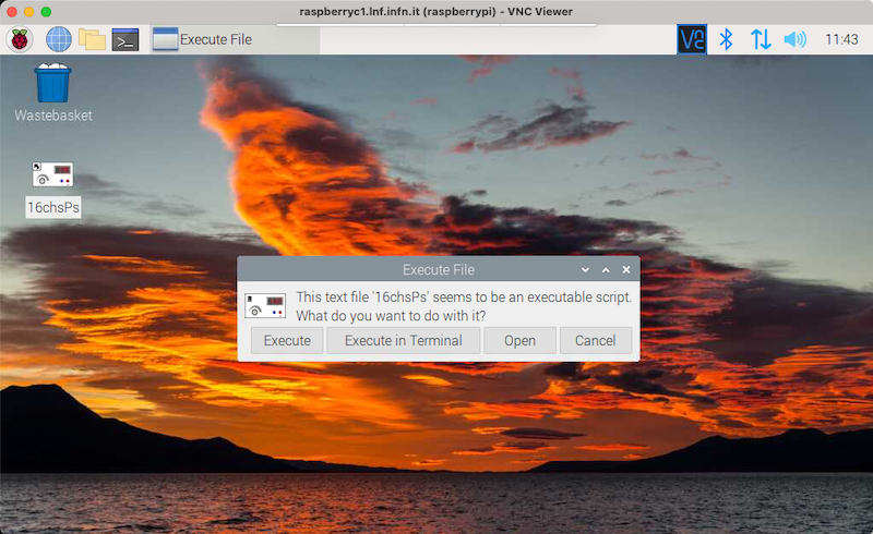
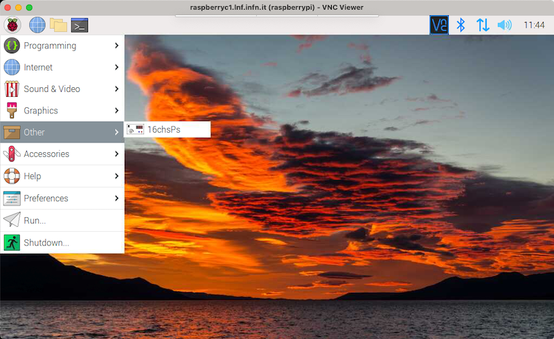
2 – Launch the GUI using the Desktop icon or the menu item
Launch GUI using Desktop icon
Launch GUI using Menu Item
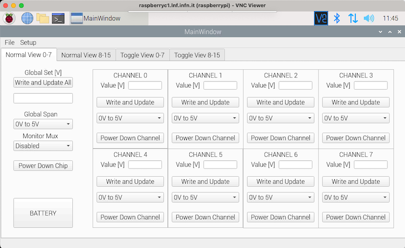
The 16 Channels Power Supply GUI
The python3 code can be downloaded from the GitHub repository.