The BES C-GEM IT High Voltage Distribution System (HVPS)
| RADIALL-REDEL box adapter | Download | Off Detector HV cable specs | Download |
| HVPP connection cables | Download | On Detector HV cable specs | Download |
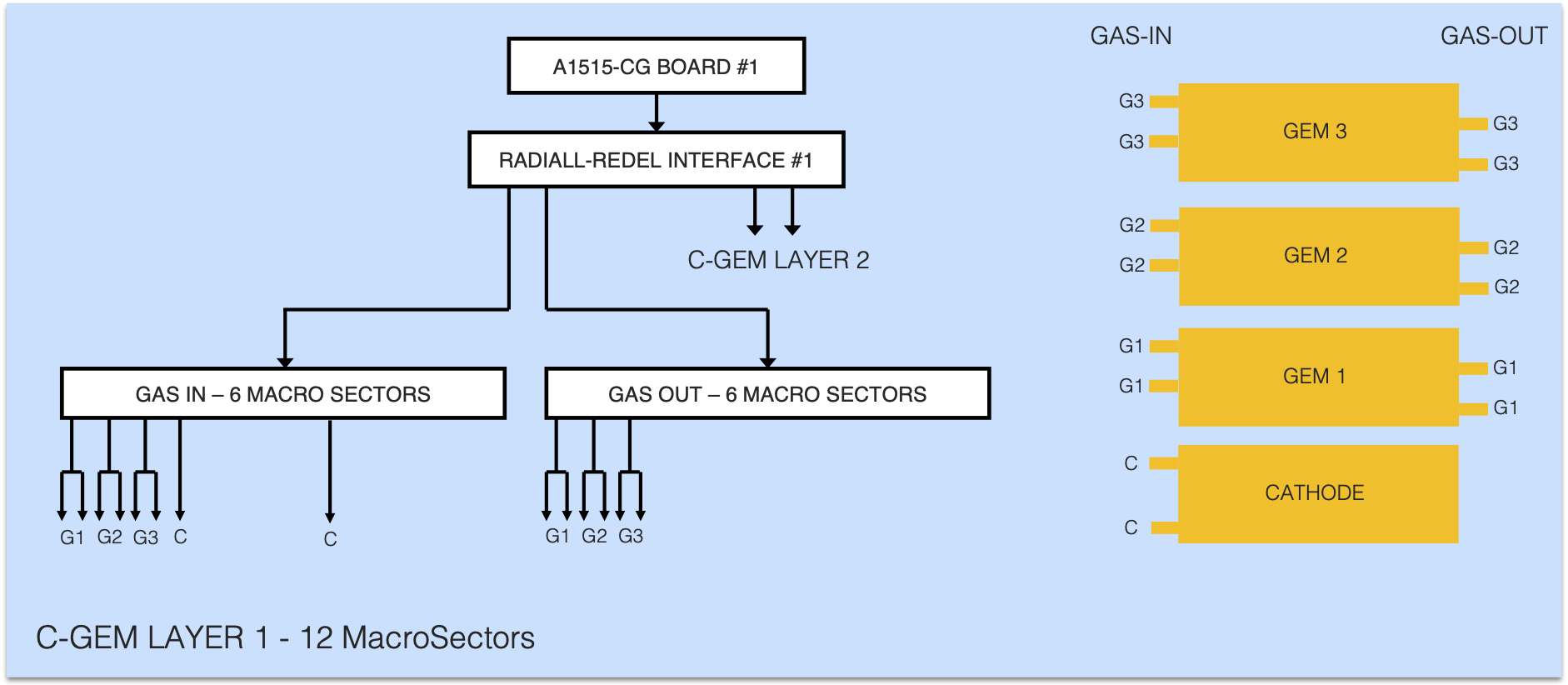
| HV Patch Panels | Download | C-GEM LAYER 1 – 12 Macro Sectors | Download |
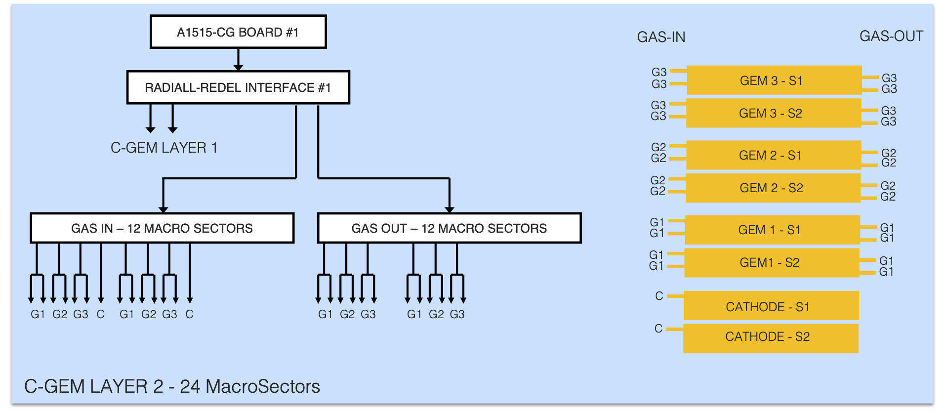
| Off-Detector Connection Cables | Download | C-GEM LAYER 2 – 24 Macro Sectors | Download |
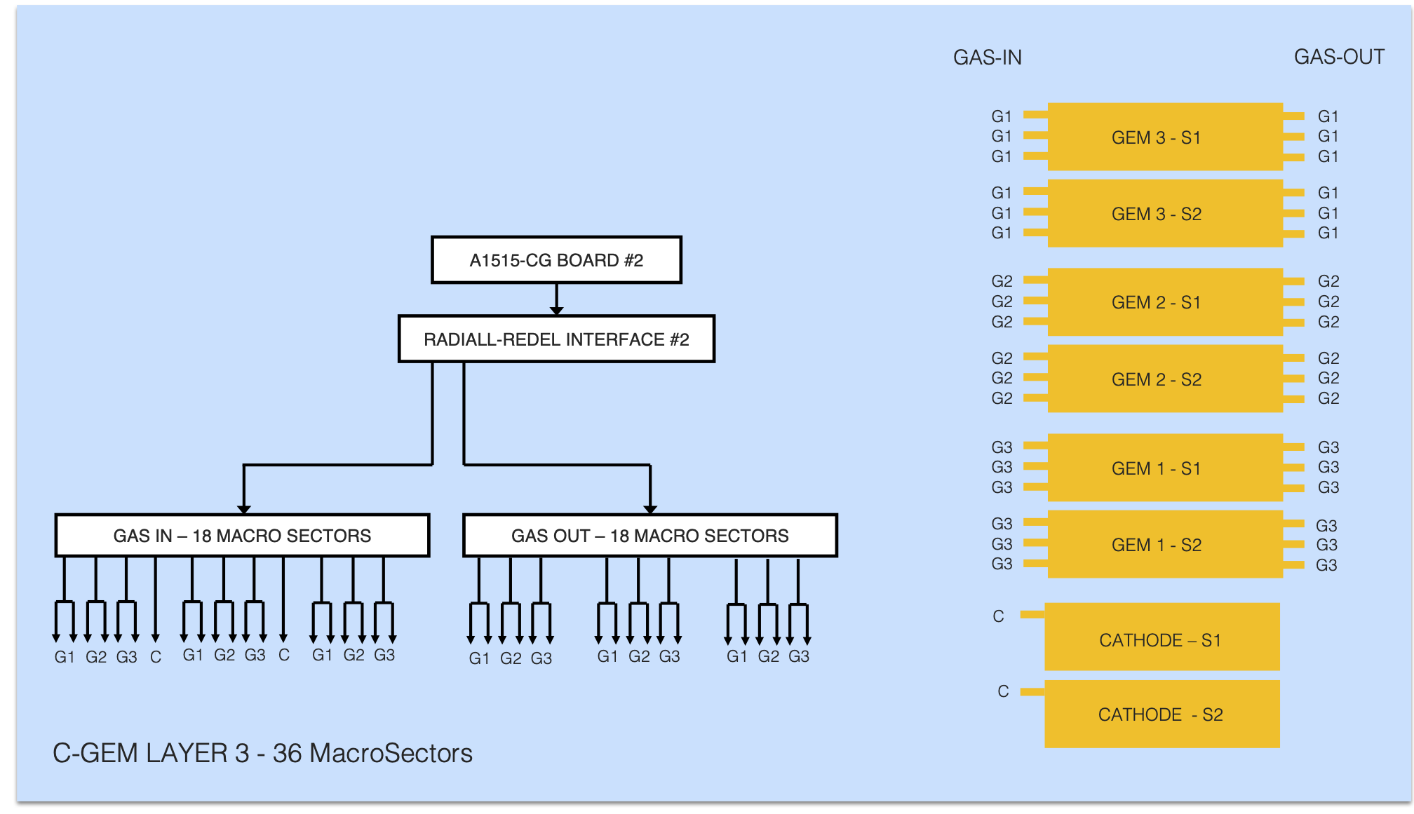
| C-GEM LAYER 3 – 36 Macro Sectors | Download |

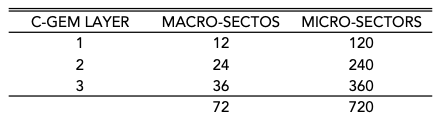
The HVPS has been designed to supply independently all the macro/micro sectors of C-GEM layers then allowing the possibility to disconnect a single micro-sector in case of C-GEM local short. The number of C-GEMs HV lines required for each layer is shown below.
macro/micro sectors for the three C-GEM tracker layers (micro sectors subdivision is required to reduce the energy involved in case of GEM discharges)
HV DISTRIBUTION OVERVIEW
The HV distribution chain is made of an active section (the A1515-CG BOARD) to generate the seven voltages required by GEMs and a passive section to split all active channels according to the number of micro-sectors per layer. As an example below is shown the block diagram of the chain used to supply 180 micro-sectors of Layer 3 (that is half half Layer 3 HV distribution chain). The main components are:
- a A1515-CG board
- an interface to split the board channels (each board is able to fully supply 2 detector layers)
- a passive distributor to split the input seven channels
- an 18 mt meter off-detector cables to distribute the sectors/micro-sectors voltages
- a 1 mt on-detector cable to connect the single sectors.
HV distribution system block diagram for Layer 3
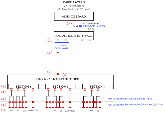
The number in parenthesis specify the connector used according to the table below while the dashed line show the border between the on/off detector components (to reduce the C-GEM weight during the insertion the system has been divided in two sections).
HV connector type and CERN SCEM (if any)

The Main Power Supply
A CAEN A1515-CG 14 channels board is used as main generator together with a SY5527LC or SY4527LC system crate (the two crate packaging and delivering power are different: the SY4527LC is a 19″-wide, 8U-high 600 W crate that can host up to 10 boards, while the SY5527LC is a 19″-wide, 4U-high 400 W crate that can host up to 4 boards). Each crate can host both High Voltage and Low Voltage boards then minimising the number of crates required to instrument the detector.
The Radial – Redel interface
Radial-Redel interface

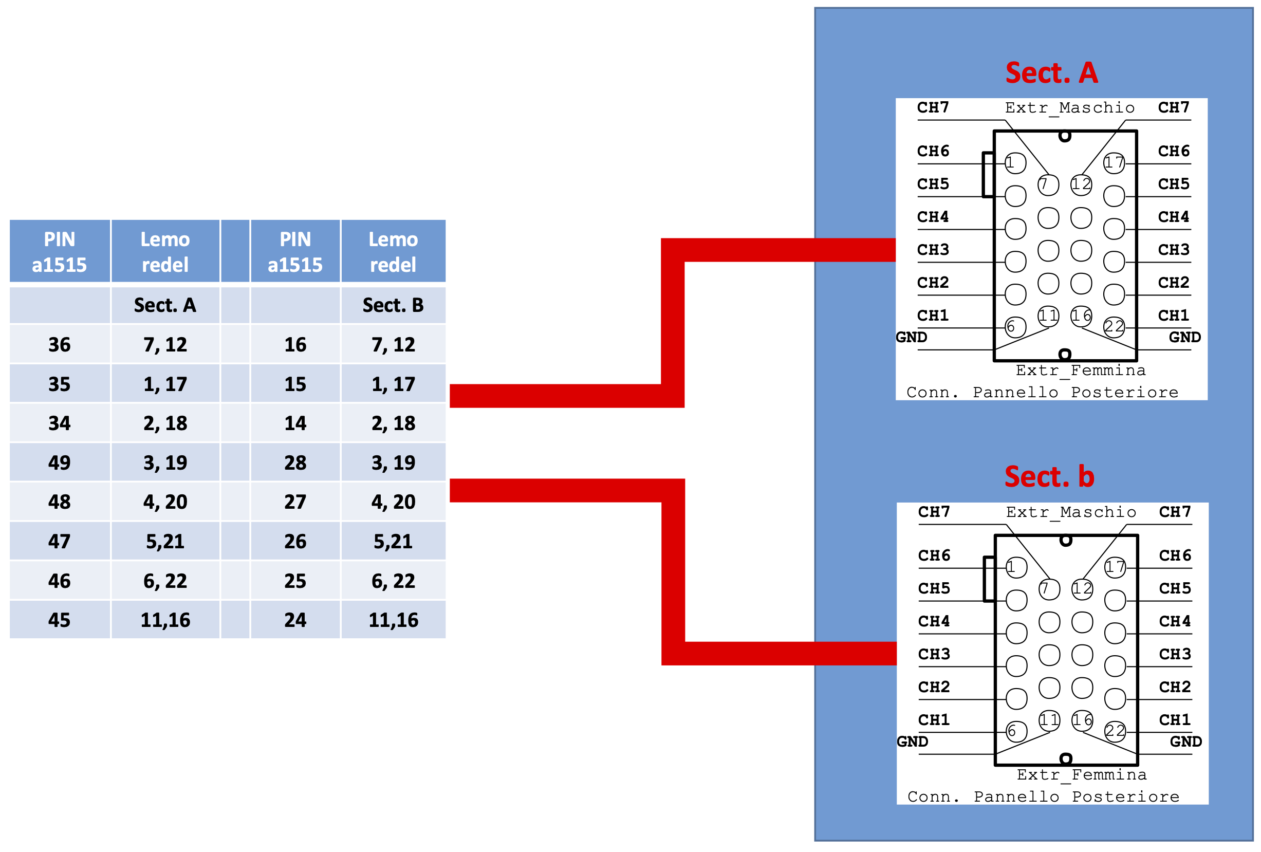
The RADIALL-REDEL interface is required to match the 52 contacts CAEN A1515-CG board output connector (RADIALL PN 691 802 002) to the 22 contacts LEMO-REDEL distributor input connector (REDEL PN KAG.H22.LLZBG). Because each layer must be supplied both in the GAS IN and GAS OUT side the interface must split each group of A1515-CG board (seven voltages and related GND return wires). The interface interconnections are shown below.
Radiall-Redel interface internal connections
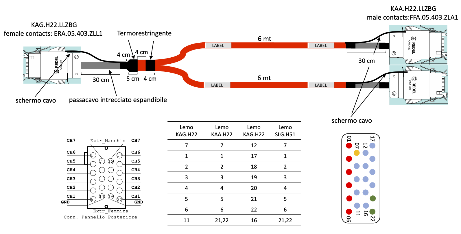
The connection to the HV Patch Panels is implemented by means of special cables providing further splitting of main voltages as shown in the picture below.
Radiall-Redel interface – HV Patch Panel interconnection cables
HV PATCH PANEL
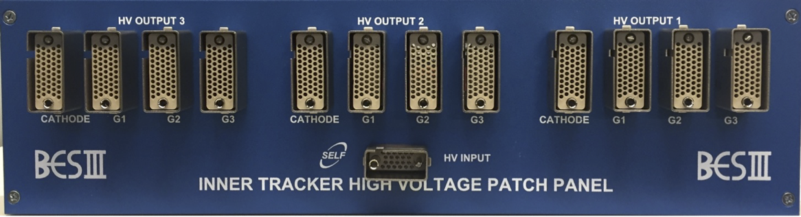
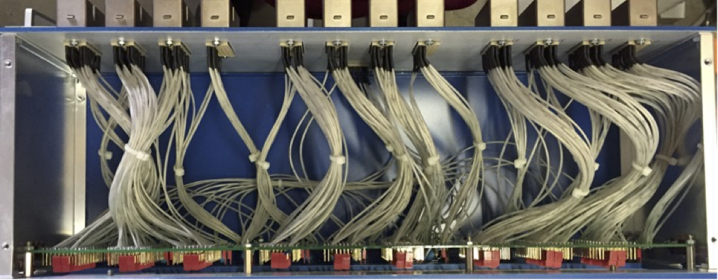
patch panel – back side
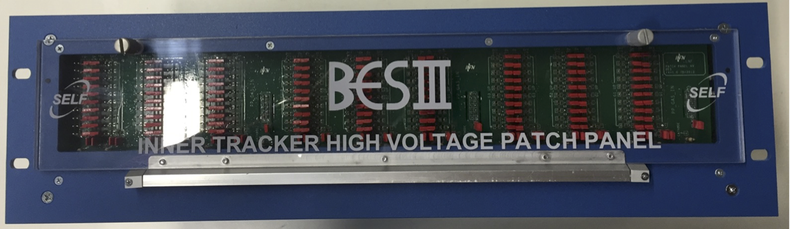
patch panel – front side
patch panel – internal connections
patch panel – connector and jumper setting for micro-sector disconnection

PATCH PANEL connector and jumper setting for micro-sector disconnection
HV SYSTEM CABLES
Both main power supplies and patch panels will be located on the platforms to simplify debug operations (in case of excess of current drown from a micro-sector), then HV cables must be routed from platforms to the detector. Because the different requirements in terms of hardness and shielding (off-detector routing) or lightness (on-detector routing) different types of cables will be used in the routing.
OFF DETECTOR CABLES

Hardness, shielding, halogen free are the main requirements for cables used to route high voltages from Patch-Panels to the apparatus. Besides, because more voltages are required to supply a macro sector (and its related 10 micro-sectors), multiple conductor, multicore cables rated up to 4.5/5 kV must be used. A 14 cores cable with these specifications has been already produced by TecniKabel for the KLOE2 Inner Tracker HV connections (cable specs) the same cable has been used for C-GEM instrumentation.
ON DETECTOR CABLES
The cable used for on-detector interconnections must be light and flexible to allow easy routing in tight spaces. Because both the shielding and the halogen-free sheath of standard cables greatly reduce cable flexibility and standard HV connectors are quite bulky, custom cable together with custom connectors have been designed for the on-detector interconnections.
1.2 mt on detector HV cable
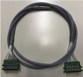
The cable has been assembled starting from extruded FEP insulated wires. By means of such wires a cable bundle with small diameter and small bending radius can be assembled. In On Detector HV cable specs are shown several FEP insulated wires produced by Teledyne Reynolds, a 18 kV AWG 28 wire size has been used in the cable bundle. No shielding is used inside the apparatus.
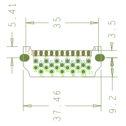
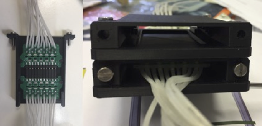
Concerning off-detector/on-detector interconnections custom connector based on light and compact PCB has been designed. The design has been greatly simplified by the low value of voltage clearance/creepage required (the maximum voltage difference between contacts is of the order of 350/400 V then allowing the use of 2.54 mm pitch connector assuming clean assembling procedure). The PCB layout is shown below together with its dimensions (female and male connections are implemented soldering male and female strips contact on the PCB).
Custom HV connector dimension