The BES C-GEM IT Low Voltage Distribution System

LV DISTRIBUTION SYSTEM MAIN FEATURES
- 80 TIGER BOARDS AND 22 GEM-ROC (DAQ) BOARDS
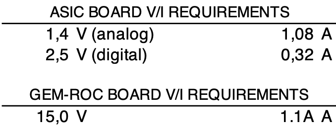
- TIGER Board V/I requirements: 1.08A@1.4V and 0.32A@2.5V (about 200W for the full detector)
- GEMROC board V/I requirements: 1.1A@15V
- Two sections:
- The main power supplies for both on-detector and off-detector electronics is located about 7 meters far from the GEMROC modules. The main power supply is made of:
- A SY5527 BASIC (600W) mainframe with four A2519 to power the GEMROCs (A2519: 32 channels, max 5 A/channel or 50 W/channel)
- A SY5527 BASIC (600W) mainframe with three A2517 boards to power the TIGER boards (A2517: 24 channels, max 5 A/channel or 50 W/channel)
- The TIGER boards distribution section is hosted in the GEMROC modules located close to the detector.
- The main power supplies for both on-detector and off-detector electronics is located about 7 meters far from the GEMROC modules. The main power supply is made of:
- The TIGER board power supply chain foresees three interconnections:
- Main power supply – GEMROC modules (7 m – four cores 13 AWG shielded cables)
- GEMROC – LV-PATCH boards (10 m – four cores 17 AWG shielded cables)
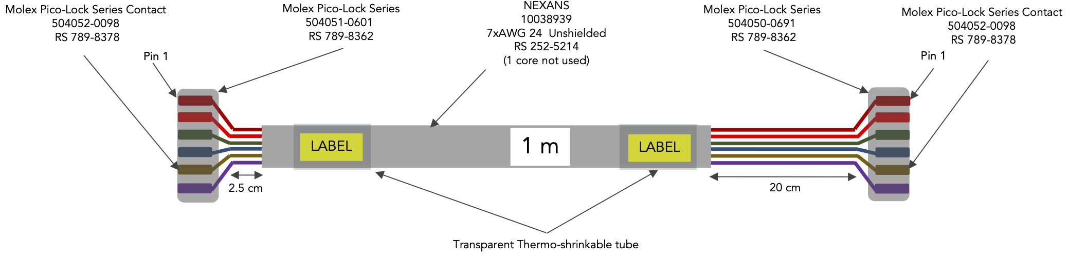
- LV-PATCH – TIGER boards (1 m – seven cores 24 AWG unshielded)
- Single channel on/off and voltage/current monitor are managed by the Experiment Slow Control system.
TIGER BOARD REQUIREMENTS
The BES C-GEM IT Low Voltage distribution system has been designed to supply C-GEM front end electronics (TIGER Boards and GEMROC) allowing the monitoring of voltages and currents together with the capability of turn on/off single channels.
The detail of the voltage/current requirements for the single Tiger Board and GEMROC are summarized below together with the current requirements for each layer of the on-detector front-end.
Tiger Boards and GEMROC Boards power requirements
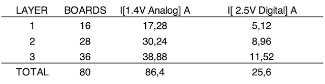
Tiger Boards power requirements for each layer
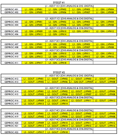
ON-DETECTOR LV DISTRIBUTION SYSTEM BLOCK DIAGRAM
- the total amount of Tiger boards (80)
- the number of power lines required by each board (analog/GND, digital/GND)
- the maximum number of channels available on each A2517 board (8 channels)
- the maximum A2517 board single channel current delivering capability (15A)
- the A2517 board single channel maximum power dissipation (50W)
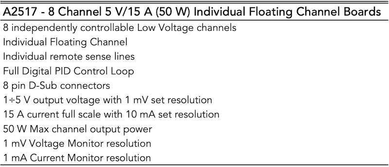
A2517 Board Main Features
The best matching has been found using a single A2517 channel to supply four TIGER boards.
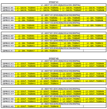
ON-DETECTOR LV BLOCK DIAGRAM
As can be inferred from the low voltage block diagram in the distribution chain there are 3 types of cables:
- the A2517 – GEMROC cable: 7 m of cable carrying (about) 9 A
- the GEMROC – DLVPC boards cable: 10 m of cable carrying (about) 1.1 A (DLVPC boards are used to interconnect on/off detector electronics)
- the DLVPC boards – TIGER Board cable: about 1 m of cable carrying (at most) 1.1A
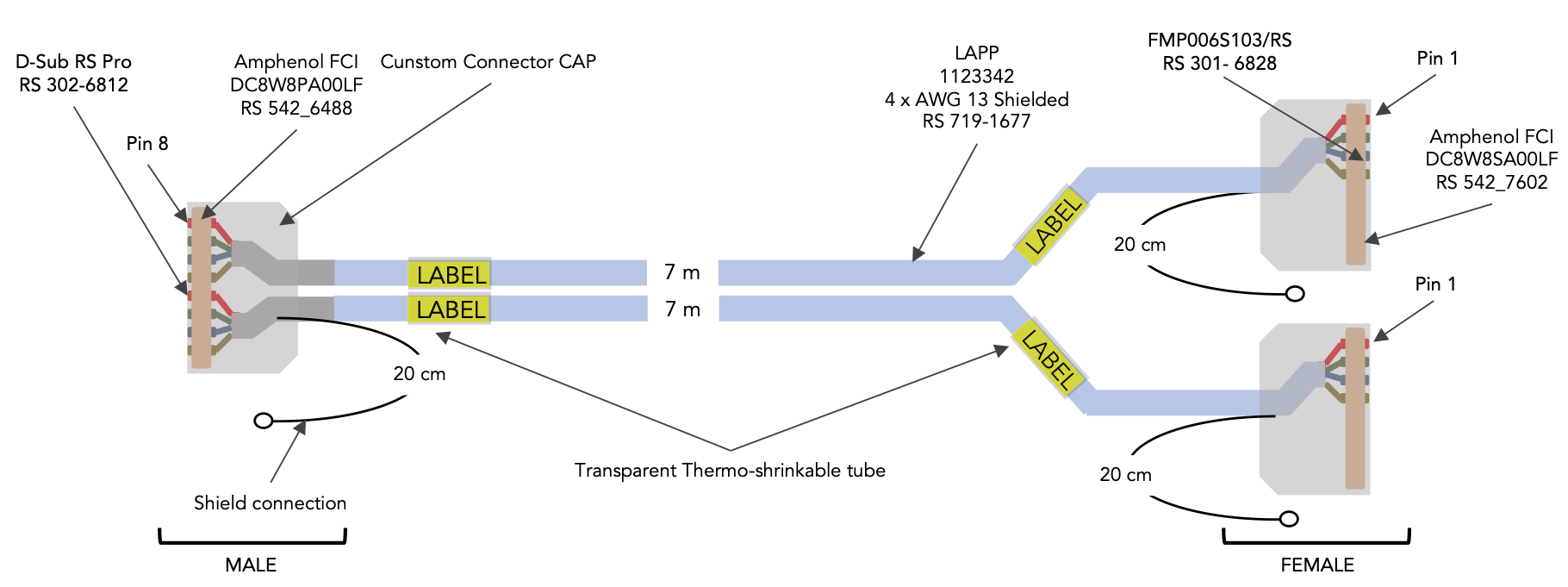
The first section of cable requires large area conductors to reduce voltage drop, moreover the cable connector must match the A2517 board connector and must be flexible enough to simplify routing.
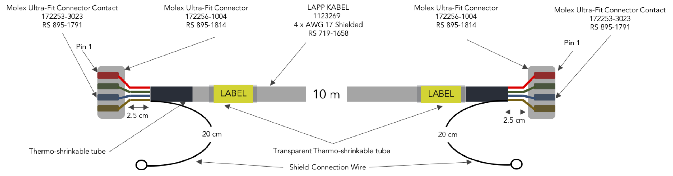
The second section of the cable connects one of the four LV distributor outputs available on each GEMROC to one DLVPC board. A four conductor AWG 17 shielded cable has been selected to match the requirements.
The last section of the cable requires high flexibility to be routed in tight spaces, then an unshielded multicore AWG24 has been selected to power the single TIGER boards.
The main features of connectors and cables used in the system are shown below together with the type of cables and the foreseen chain voltage drop (about 2 V).
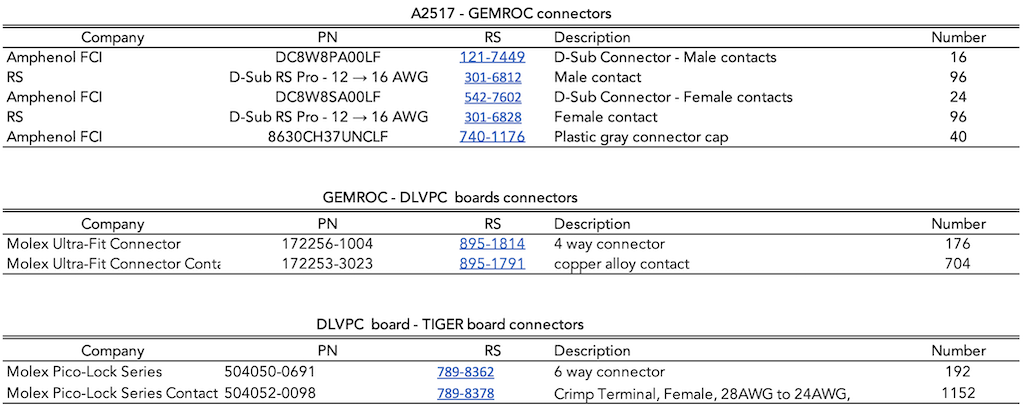
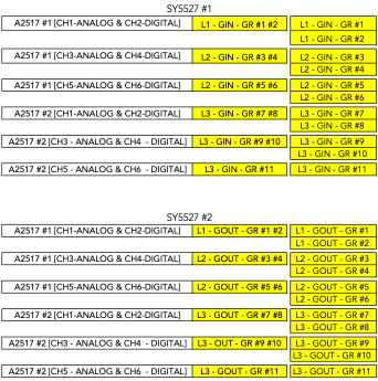
LV chain connection
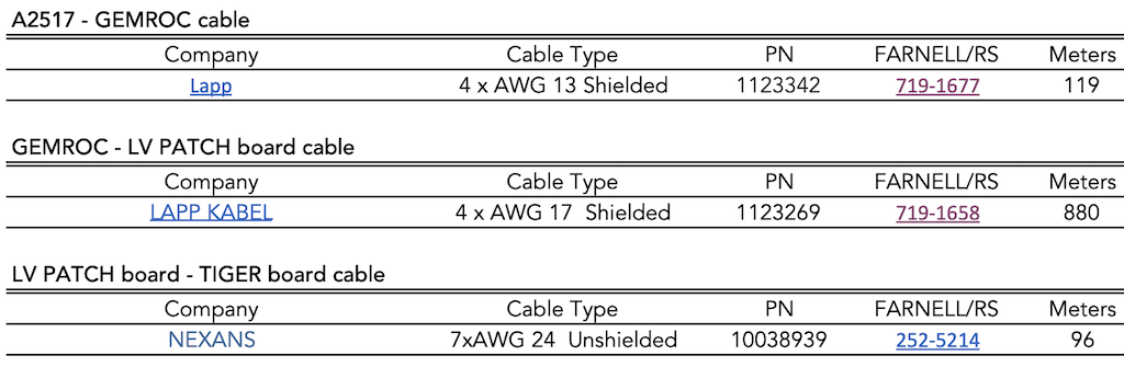
LV chain cables
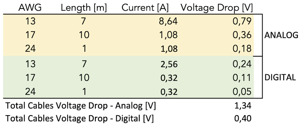
Cables voltage drop
Label cable type 1_1
Label cable type 2
Label cable type 3
Cable type_1_1
Cable type_2