
CARIOCA – VMM3 COMPARISON
| CARIOCA | VMM3 | |
|---|---|---|
| Zin | ≅10 ohm (in the preamplifier BW) [1] | ≅50-70 ohm (in the preamplifier BW) [1] |
| Input Polarity | pos/neg | pos/neg |
| Input Range | ≅ 200 fC | ≅ 2 pC |
| Gain | 8 mV/fC | 0.5 – 16 mV/fC |
| Peaking Time | 14 + 0.007 x Cdet | 25-50-100-200 ns |
| Time Walk | ≅ 12 ns (range: 10-150 fC) | < 3 ns (range: 10-100 fC; Cin= 200pF; peaking time = 25 ns) |
| Noise | 416 e + 54 e/pF | 11000 e @ 200 pF & 25 ns peaking time |
| Time Measurement | NO | 60-650 ns (60 ns @ 6 bits; 8 bits max) |
| Charge Measurement | NO | 10 bits @ 200 ns |
| PD | 12 mW/ch @ 2.5 V | 10 mW/ch [2] |
| Data Out | discriminated values | 38 bits/hit (+ 2 bits: 40 bits transmitted) |
| Digital Out | parallel | 560 Mbits/s (2 x 160 MHz DDR; 8b/10b protocol) |
[1] In the preamplifier BW
[2] Nominal (1 W probable value)
CARIOCA PLOTS
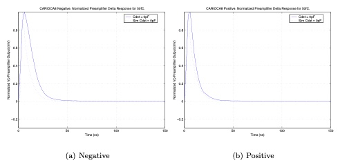
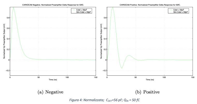
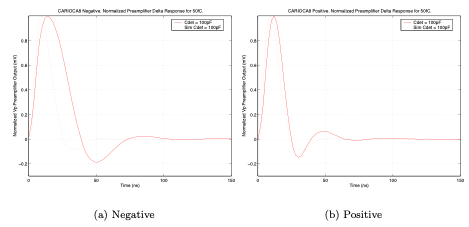
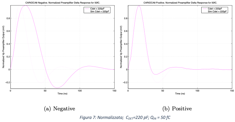
CARIOCA SHAPING
δ response @ Cdet = 0 pF Qin = 50 fC (dashed = simulation, solid = measure)
δ response @ Cdet = 56 pF Qin = 50 fC (dashed = simulation, solid = measure)
δ response @ Cdet = 100 pF Qin = 50 fC (dashed = simulation, solid = measure)
δ response @ Cdet = 220 pF Qin = 50 fC (dashed = simulation, solid = measure)
CARIOCA NOISE
Negative input noise = 2460 + 50e/pF; Positive input noise = 2157 + 50e/pF
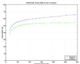
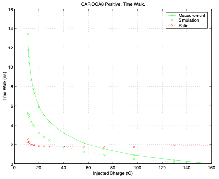
CARIOCA TIME WALK
CARIOCA8 time walk negative
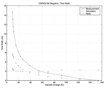
CARIOCA8 time walk negative
VMM3 PLOTS
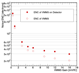
VMM3 NOISE
VMM3 Noise (unknown detector capacitance)
VMM3 PD @ 1.2V
- Vddp: Charge amplifier supply connected to the sources of the p-channel input MOSFETs (max. ≃ 150 mA)
- Vdd: Power all other analog circuits (max. ≃ 400 mA)
- Vddad: Mixed Analog-digital (ADC) (max. ≃ 200 mA)
- Vdd: Supplies digital circuits and ALVS drivers (max. ≃ 150 mA)
Total PD ≃ 400-800 mW ( 1W/chip cooling required)
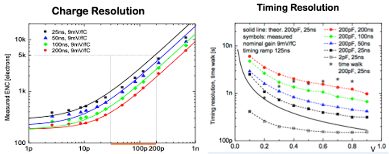
VMM3 CHARGE & TIME RES vs Cdet
VMM3 CONTINOUS RO MODE
In continuer readout mode the VMM3 can manage up to 4 MHz of input rates per channel when using the 10 bits ADC for charge and 8 bits for time (250 ns conversion time). The input rate can be further increased limiting to 6 the number of bits. When conversion is completed the digital value is stored in memory and the channel goes in the self reset procedure the providing continuous and independent operation of all the 64 channels.
Event data are stored in a 4-event deep de-randomizing FIFO for each single channel (problems in using the FIFO have been mentioned is some paper)